Recent Posts

Tuesday, 31 January 2017

Connection of the motor winding:

There are several ways of connecting a three phase motor winding . The most common ones
3-phase connection are:

1)delta(∆)-connection  
2)star (Y)-connection.

3-phase connection of induction motor winding
According to the IEC 60034-8 standard, the windings of a 3-phase standard motor can be connected in either a star (Y)-connection or in a delta (∆)-connection.

Star (Y)-connection:

By short-circuiting the terminals W2, U2 and V2 and connecting the mains to W1, U1 and V1, you get a star (Y)-connection. 

star connected 3 phase motor winding connection diagram
Fig:star connected 3 phase motor winding connection diagram
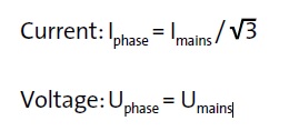
current in star connected induction motor winding connection
fig:Fig: current in star connected motor winding


Delta (∆)-connection:

When you connect the end of a phase to the start of another phase you get a delta (∆)-connection 
i.e  W2-U1, U2-V1, V2-W1 as shown in figure by connecting main supply to U1 V1 W1
                  Fig: delta connected 3 phase motor winding connection diagram


current in delta connected induction motor winding
Fig:delta connected motor winding current


Monday, 30 January 2017


Different types of Induction motor protection given below:

Introduction of motor protection:
Electric motors are exposed to many kinds of disturbances and stress. Part of the disturbances is due to imposed external conditions such as over voltage and undervoltage, over frequency and underfrequency, harmonics, unbalanced system voltages and supply interruptions,  Other possible causes of external disturbances are dirt in the motor, cooling system and bearing failures or increase of ambient temperature and humidity. Stress on motor due to frequent successive startups,overload situations including mechanical stress. The above stress and disturbances deteriorate the winding insulation of the motor mechanically and by increased thermal ageing rate, which may eventually lead to an insulation failure.
The purpose of the motor protection is to limit the effects of the disturbances and stress factors to a safe level, for example, by limiting overvoltages or by preventing too frequent startup attempts. If, however, a motor failure takes place, the purpose of the protection is to disconnect the motor from the supplying network in due time
Motor overload condition is mainly a result from abnormal use of the motor, harmonics or unbalanced supply voltages. They all increase the motor losses and cause additional heating. As the temperature exceeds the rated limits specified for the insulation class, the winding insulation deterioration startup. This will reduced the expected lifetime of the motor and may lead to an electrical fault in the winding. Thus, the thermal overload protection can be
considered being the most important protection function

2) Thermal Model 
The thermal behavior of the stator and the rotor during startups and during constant overload situations differs significantly from each other. Due to this fact, the dynamics of the motor heating and cooling is typically designed separately for the stator and for the rotor of motor. Designing the thermal overload protection in this way, it can be set to follow the thermal state of the motor optimally, and good and accurate protection against both short and long-time overload conditions can be accomplished, which allows the full use of the available capacity.

3) Frequent Startup Supervision:

In order avoid, shorten the expected lifetime of the motor, there must be an adequate time interval between successive startups of motors. Therefore, a certain starting frequency, that is, the number of startups per hour specified for the motor, must not be exceeded.Especially during successive startups, the temperature of the rotor rises and drops rapidly whereas the temperature of the stator changes much more slowly. At rated load, the temperature of the rotor is much lower than the temperature of the stator.If after a startup the motor is running for some time before stopping, the rotor has enough time to cool down. Then whether a restart can be done or not depends totally on the stator temperature, which can be a limiting factor. On the other hand, if the initial start had been done from a cold condition and it failed for
some reason, then whether a restart can be done or not depends now totally on the rotor temperature, which can be a limiting factor instead. If the initial start had been done from hot condition, then the limiting factor is again the stator temperature. this kind of thermal behavior simulated with the two-time-constant model for the stator and for the rotor.


4) Overload Protection
A minor overload does not cause a motor failure immediately but it will eventually shorten the expected lifetime. On the other hand, a constant overload can be a sign of some kind of disturbance in the process in which the motor drive is being used. Thus, a two-stage overload protection is preferred. The alarming stage gives an indication that the rated load of the motor with a possible margin has been exceeded. This function can be implemented by a pre-warning temperature level setting in the thermal model. The pre-warning alarm gives the operator some time to find out the possible source of the overload and to attempt to remove it. If the overload becomes higher, for example 10-15%, the tripping stage starts and trips the motor feeder in due time unless the source of the overload has disappeared before that. According to the thermal model,tripping takes place when the estimated thermal level exceeds 100%. shows an example of the thermal behavior when the motor is running on a constant cyclic overload. These curves have been simulated using the two-time-constant model for the stator and for the rotor. In this case, the prewarninglevel is exceeded and the operator is notified. As a result, the tripping is prevented as the loading of the motor becomes suitably reduced. It can also be concluded from that a comprehensive overload protection in fact requires the use of the two-time-constant model for the rotor and for the stator, and in this way, the full utilization of the available capacity of the motor is ensured. However, adequate protection can also be implemented using the single-time-constant model, which is set to allow the normal use of the motor drive with a suitable margin
 

5)Overheating Protection
The motor temperature can rise above the rated values allowed for the stator and for the rotor even if the motor is not actually being overloaded. Possible reasons for this are dirt in the motor, failures in the cooling system or harmonic currents. Especially in case of variable frequency drives, overheating may take place if the motor is being loaded with rated current simultaneously with low rotating speed because of the increased losses and reduced cooling.

i) Stator Earth-fault Protection

As the winding insulation deteriorates due to ageing processes, instantly imposed severe thermal or mechanical stress may exceed the withstanding level, leading to an insulation breakdown. Usually, this results in an earth fault, where the fault current flows through the stator iron plates. If the current is less than 10A,only alarming protection can typically be considered. With a higher fault, current tripping is recommended as the damages to the stator iron may become substantial. 

ii) Short Circuit and Inter-winding Fault Protection:
Sustained earth fault in the motor can develop to a short circuit fault between the phase windings. Another possible cause is the out-of-phase re-energizing during autoreclosing when high mechanical stress may shake and vibrate the windings so that the insulation between the windings breaks. This kind of fault must be tripped as fast as possible to minimize further damages. Usually a high-set overcurrent stage is used for the protection. This function also constitutes the short circuit protection of the supplying cable. Also with bigger machines, differential protection can be considered if the neutral point with suitable CTs are available.

Different types of Induction motor protection given below:

Introduction of motor protection:
Electric motors are exposed to many kinds of disturbances and stress. Part of the disturbances is due to imposed external conditions such as over voltage and undervoltage, over frequency and underfrequency, harmonics, unbalanced system voltages and supply interruptions,  Other possible causes of external disturbances are dirt in the motor, cooling system and bearing failures or increase of ambient temperature and humidity. Stress on motor due to frequent successive startups,overload situations including mechanical stress. The above stress and disturbances deteriorate the winding insulation of the motor mechanically and by increased thermal ageing rate, which may eventually lead to an insulation failure.
The purpose of the motor protection is to limit the effects of the disturbances and stress factors to a safe level, for example, by limiting overvoltages or by preventing too frequent startup attempts. If, however, a motor failure takes place, the purpose of the protection is to disconnect the motor from the supplying network in due time
Motor overload condition is mainly a result from abnormal use of the motor, harmonics or unbalanced supply voltages. They all increase the motor losses and cause additional heating. As the temperature exceeds the rated limits specified for the insulation class, the winding insulation deterioration startup. This will reduced the expected lifetime of the motor and may lead to an electrical fault in the winding. Thus, the thermal overload protection can be
considered being the most important protection function

2) Thermal Model 
The thermal behavior of the stator and the rotor during startups and during constant overload situations differs significantly from each other. Due to this fact, the dynamics of the motor heating and cooling is typically designed separately for the stator and for the rotor of motor. Designing the thermal overload protection in this way, it can be set to follow the thermal state of the motor optimally, and good and accurate protection against both short and long-time overload conditions can be accomplished, which allows the full use of the available capacity.

3) Frequent Startup Supervision:

In order avoid, shorten the expected lifetime of the motor, there must be an adequate time interval between successive startups of motors. Therefore, a certain starting frequency, that is, the number of startups per hour specified for the motor, must not be exceeded.Especially during successive startups, the temperature of the rotor rises and drops rapidly whereas the temperature of the stator changes much more slowly. At rated load, the temperature of the rotor is much lower than the temperature of the stator.If after a startup the motor is running for some time before stopping, the rotor has enough time to cool down. Then whether a restart can be done or not depends totally on the stator temperature, which can be a limiting factor. On the other hand, if the initial start had been done from a cold condition and it failed for
some reason, then whether a restart can be done or not depends now totally on the rotor temperature, which can be a limiting factor instead. If the initial start had been done from hot condition, then the limiting factor is again the stator temperature. this kind of thermal behavior simulated with the two-time-constant model for the stator and for the rotor.


4) Overload Protection
A minor overload does not cause a motor failure immediately but it will eventually shorten the expected lifetime. On the other hand, a constant overload can be a sign of some kind of disturbance in the process in which the motor drive is being used. Thus, a two-stage overload protection is preferred. The alarming stage gives an indication that the rated load of the motor with a possible margin has been exceeded. This function can be implemented by a pre-warning temperature level setting in the thermal model. The pre-warning alarm gives the operator some time to find out the possible source of the overload and to attempt to remove it. If the overload becomes higher, for example 10-15%, the tripping stage starts and trips the motor feeder in due time unless the source of the overload has disappeared before that. According to the thermal model,tripping takes place when the estimated thermal level exceeds 100%. shows an example of the thermal behavior when the motor is running on a constant cyclic overload. These curves have been simulated using the two-time-constant model for the stator and for the rotor. In this case, the prewarninglevel is exceeded and the operator is notified. As a result, the tripping is prevented as the loading of the motor becomes suitably reduced. It can also be concluded from that a comprehensive overload protection in fact requires the use of the two-time-constant model for the rotor and for the stator, and in this way, the full utilization of the available capacity of the motor is ensured. However, adequate protection can also be implemented using the single-time-constant model, which is set to allow the normal use of the motor drive with a suitable margin
 

5)Overheating Protection
The motor temperature can rise above the rated values allowed for the stator and for the rotor even if the motor is not actually being overloaded. Possible reasons for this are dirt in the motor, failures in the cooling system or harmonic currents. Especially in case of variable frequency drives, overheating may take place if the motor is being loaded with rated current simultaneously with low rotating speed because of the increased losses and reduced cooling.

i) Stator Earth-fault Protection

As the winding insulation deteriorates due to ageing processes, instantly imposed severe thermal or mechanical stress may exceed the withstanding level, leading to an insulation breakdown. Usually, this results in an earth fault, where the fault current flows through the stator iron plates. If the current is less than 10A,only alarming protection can typically be considered. With a higher fault, current tripping is recommended as the damages to the stator iron may become substantial. 

ii) Short Circuit and Inter-winding Fault Protection:
Sustained earth fault in the motor can develop to a short circuit fault between the phase windings. Another possible cause is the out-of-phase re-energizing during autoreclosing when high mechanical stress may shake and vibrate the windings so that the insulation between the windings breaks. This kind of fault must be tripped as fast as possible to minimize further damages. Usually a high-set overcurrent stage is used for the protection. This function also constitutes the short circuit protection of the supplying cable. Also with bigger machines, differential protection can be considered if the neutral point with suitable CTs are available.

Sunday, 29 January 2017

Lighting transformer used in industries
What is lighting transformer and why lighting transformer used
Fig: Type of Lighting Transformers

Lighting Transformers are designed to supply power to lighting equipment in a commercial / industrial / domestic unit. Its primary supply connected to higher voltage source and secondary is to be connected to load.  

Lighting transformers serves as isolation between primary and secondary, it also restricts any high voltage spikes and EMF coming with the raw mains incoming power. It also restricts short circuit current in the load and saves major accidents.
It is also used where incoming supply is 3 phase 3 wire and lighting load is 220 Volt single phase.
Power House lighting transformers are made with CRGO laminations and Electrolytic copper super enameled winding wires.
They are available for wide range of inputs out are in the range and in capacity from 15 VA to 50 KVA.
Lighting transformer used only for lighting purpose. As power transformer used for providing power like motor, heater, UPS, chiller, grinder, welding machines, and other electrical equipment other than lighting and lighting transformer are used only for lighting purpose.

Benefits of lighting transformer

 As lighting transformer having tap changing facility we can adjust secondary supply voltage.
By using lighting transformer life of electrical equipment increased (bulb, tubelight, etc ).
As the lighting transformer work as isolation transformer the system is safe from voltage spikes.

Providing lighting load through lighting transformer is much better and safe than providing through power transformer. 

Saturday, 28 January 2017

Calculation of current drawn by motor under different load condition like full load,on no load condition are given below for 
1 phase 230 & 3 phase 440v supply:

1) Single Phase Motor draws Current = 7Amp per HP.

2) 3 Phase Motor draws Current = 1.5Amp per HP.

3) Full Load Current of three Phase Motor = HPx1.25
 
4) Full Load Current of single Phase Motor = HPx6

5) KW Rating of Motor = HPx0.75

Saturday, 21 January 2017

How does diesel generator(induction generator) work?


When induction motor running as generator it takes mechanical power and supply electrical power from stator. To run the induction motor as generator, it's slip must be less than zero. i.e negative
Negative slip show that the rotor is running at a speed above the synchronous speed. Thus when slip of induction motor is negative means induction motor runs faster than synchronous speed, the induction motor runs as a generator called induction generator.

Explanation about How does an alternator work?
 

simple electric generator diagram given below:
 How does a generator work? generator working principle explanation
fig:generator working principle
If a simple loop of wire is rotated between the poles of a permanent magnet, as shown in Fig the loop of wire will cut the lines of magnetic flux between the north and south poles. This flux cutting will induce an emf in the wire by Faraday’s law which states that when a conductor cuts or is cut by a magnetic field, an emf is induced in that conductor. If the generated emf is collected by carbon brushes at the slip rings and displayed on the screen of a cathode ray oscilloscope, the wave form will be seen to be approximately sinusoidal.Alternately changing, first positive and then negative,then positive again, giving an alternating output

Main parts of a generator
The main components of an electric generator can be broadly classified as follows:
(1) Engine
(2) Alternator
(3) Fuel tank
(4) Voltage Regulator
(5) Cooling Systems
(6) Lubrication System
(7) Battery Charger
(8) Control Panel
(9) Main Assembly

Explanation of the main part of a induction generator is given below.

1) Engine
The engine is the source of the input mechanical energy to the generator. The size of the engine is directly proportional to the maximum power output the generator can supply. There are several factors that you need to keep in mind while assessing the engine of your generator. The manufacturer of the engine should be consulted to obtain full engine operation specifications and maintenance schedules.Generator engines operate on a variety of fuels such as diesel, gasoline, propane, or natural gas. Smaller engines usually operate on gasoline while larger engines run on diesel, liquid propane, propane gas, or natural gas .


(2) Alternator
The alternator, also known as the ‘generator ’, is the part of the generator that produces the electrical output from the mechanical input supplied by the engine. It contains an assembly of stationary and moving parts encased in a housing. The components work together to cause relative movement between the magnetic and electric fields, which in turn generates electricity.

(a) Stator – This is the stationary part of generator. It contains a starter winding.

(b) Rotor or armature – This is rotating part of generator which produces a rotating magnetic field (RMF) in any one of the following three ways:
(i) By induction – These are known as brushless alternators and are usually used in large   generators.
(ii) By permanent magnets – This is common in small alternator units.
(iii) By using an exciter – An exciter is a small source of direct current (DC) that energizes the rotor through an assembly of conducting slip rings and brushes.
The rotor generates a moving magnetic field around the stator, which induces a voltage difference between the windings of the stator. This produces the alternating current (AC) output of the generator.
The following are the factors that you need to keep in mind while assessing the alternator of a generator:
(a) Metal versus Plastic Housing – An all-metal design ensures durability of the alternator. Plastic housings get deformed with time and cause the moving parts of the alternator to be exposed. This increases wear and tear and more importantly, is hazardous to the user.
(b) Ball Bearings versus Needle Bearings – Ball bearings are preferred and last longer.
(c) Brushless Design – An alternator that does not use brushes requires less maintenance and also produces cleaner power.
(3) Fuel tank
The fuel tank usually has sufficient capacity to keep the generator operational for long hours on an average. In the case of small generator units, the fuel tank is a part of the generator’s skid base or is mounted on top of the generator frame. For commercial applications, it may be necessary to erect and install an external fuel tank. All such installations are subject to the approval of the City Planning Division.  Click the following link for further details regarding fuel tanks for generators.
Common features of the fuel system include the following:
(a) Pipe connection from fuel tank to engine – The supply line directs fuel from the tank to the engine and the return line directs fuel from the engine to the tank.
(b) Ventilation pipe for fuel tank – The fuel tank has a ventilation pipe to prevent the build-up of pressure or vacuum during refilling and drainage of the tank. When you refill the fuel tank, ensure metal-to-metal contact between the filler nozzle and the fuel tank to avoid sparks.
(c) Overflow connection from fuel tank to the drain pipe – This is required so that any overflow during refilling of the tank does not cause spillage of the liquid on the generator set.
(d) Fuel pump – This transfers fuel from the main storage tank to the day tank. The fuel pump is typically electrically operated.
(e) Fuel Water Separator / Fuel Filter – This separates water and foreign matter from the liquid fuel to protect other components of the generator from corrosion and contamination.
(f) Fuel Injector – This atomizes the liquid fuel and sprays the required amount of fuel into the combustion chamber of the engine.
(4) Voltage Regulator Exciter Windings
(1) Voltage Regulator: Conversion of AC Voltage to DC Current – The voltage regulator takes up a small portion of the generator’s output of AC voltage and converts it into DC current. The voltage regulator then feeds this DC current to a set of secondary windings in the stator, known as exciter windings.
(2) Exciter Windings: Conversion of DC Current to AC Current – The exciter windings now function similar to the primary stator windings and generate a small AC current. The exciter windings are connected to units known as rotating rectifiers.


(5) Cooling Systems in generator
(a) Cooling System
Continuous usage of the generator causes its various components to get heated up. It is essential to have a cooling and ventilation system to withdraw heat produced in the process.
Raw/fresh water is sometimes  used as a coolant for generators, but these are mostly limited to specific situations like small generators in city applications or very large units over 2250 kW and above. Hydrogen is sometimes used as a coolant for the stator windings of large generator units since it is more efficient at absorbing heat than other coolants. Hydrogen removes heat from the generator and transfers it through a heat exchanger into a secondary cooling circuit that contains de-mineralized water as a coolant. This is why very large generators and small power plants often have large cooling towers next to them.  For all other common applications, both residential and industrial, a standard radiator and fan is mounted on the generator and works as the primary cooling system.
(b) Exhaust System
Exhaust fumes emitted by a generator are just like exhaust from any other diesel or gasonline engine and contain highly toxic chemicals that need to be properly managed. Hence, it is essential to install an adequate exhaust system to dispose of the exhaust gases.  This point can not be emphasized enough as carbon monoxide poisoning remains one of the most common causes for death in post hurricane affected areas because people tend to not even think about it until it’s too late. 
Exhaust pipes are usually made of cast iron, wrought iron, or steel. These need to be freestanding and should not be supported by the engine of the generator. Exhaust pipes are usually attached to the engine using flexible connectors to minimize vibrations and prevent damage to the generator’s exhaust system. The exhaust pipe terminates outdoors and leads away from doors, windows and other openings to the house or building. You must ensure that the exhaust system of your generator is not connected to that of any other equipment. You should also consult the local city ordinances to determine whether your generator operation will need to obtain an approval from the local authorities to ensure you are conforming to local laws a protect against fines and other penalties.
(6) Lubricating System
An internal combustion engine would not last long if the moving parts of engine allowed to run metal-to-metal contact. The heat generated due to the tremendous amounts of friction would melt the metals, leading to the destruction of the engine. To prevent this, all moving parts ride on a thin film of oil that is pumped between all the moving parts of the engine.
Once between the moving parts, the oil serves two purposes. One purpose is to lubricate the bearing surfaces. The other purpose is to cool the bearings by absorbing the friction generated heat. The flow of oil to the moving parts is accomplished by the engine's internal lubricating system
(7) Battery Charger
The start function of a generator is battery-operated. The battery charger keeps the generator battery charged by supplying it with a precise ‘float’ voltage. If the float voltage is very low, the battery will remain undercharged. If the float voltage is very high, it will shorten the life of the battery. Battery chargers are usually made of stainless steel to prevent corrosion. They are also fully automatic and do not require any adjustments to be made or any settings to be changed. The DC output voltage of the battery charger is set at 2.33 Volts per cell, which is the precise float voltage for lead acid batteries. The battery charger has an isolated DC voltage output that does interfere with the normal functioning of the generator.
(8) Control Panel
A control panel is a set of displays that indicate the measurement of various parameters like voltage, current and frequency, through gauges and meters. These meters and gauges are set in a metallic body, usually corrosion proof, to protect from the effect of rain or snow. The panel may be set up on the body of the generator itself
In auto start control panels automatically start your generator during a power outage, monitor the generator while in operation, and automatically shut down the unit when no longer required.
(a) Engine gauges are different gauges indicate important parameters such as oil pressure, temperature of coolant, battery voltage, engine rotation speed, and duration of operation. Constant measurement and monitoring of these parameters enables built-in shut down of the generator when any of these cross their respective threshold levels.
(b) Generator gauges – The control panel also has meters for the measurement of output current and voltage, and operating frequency.
(d) Other controls – Phase selector switch, frequency switch, and engine control switch (manual mode, auto mode) among others.
(9) Frame
All generators, portable or stationary, have customized housings that provide a structural base support. The frame also allows for the generated to be earthed for safety.
generator working video tutorial

Monday, 16 January 2017

 content:
                 Direct current (DC)
                 Main applications of direct current 
                 various factors for the interruption of direct current
                 selection of circuit-breakers for direct current


Direct current (DC) is the unidirectional flow of electric charge. Direct current is produced by sources such as batteries, power supplies, thermocouples, solar cells.Direct current may be obtained from an alternating current supply by using rectifier
Direct current (DC) application ans uses
direct current wave form

dc voltage wave form

Main applications of direct current
direct current (DC) used in many application due to its unique feature that is its storage facility


1) Emergency supply or auxiliary services:

the use of direct current is due to the need to employ a back-up energy
source which allows the supply of essential services such as protection
services, emergency lighting, alarm systems, hospital and industrial services,
data-processing centres etc., using accumulator batteries, for example.
 

2)  Electrical traction:

the advantages offered by the use of dc motors in terms of regulation and of
single supply lines lead to the widespread use of direct current for railways,
underground railways, trams, lifts and public transport in general.
 

3) Particular industrial installations:

there are some electrolytic process plants and applications which have a
particular need for the use of electrical machinery.
Typical uses of circuit-breakers include the protection of cables, devices and
the operation of motors.

Considerations for the interruption of direct current


Direct current presents larger problems than alternating current does in terms
of the phenomena associated with the interruption of high currents. 

Alternating currents have a natural passage to zero of the current every half-cycle, which corresponds to a spontaneous extinguishing of the arc which is formed when
the circuit is opened.This characteristic does not exist in direct currents, and furthermore, in order to extinguish the arc, it is necessary that the current lowers to zero.
The extinguishing time of a direct current, all other conditions being equal, is
proportional to the time constant of the circuit T = L/R.
It is necessary that the interruption takes place gradually, without a sudden
switching off of the current which could cause large over-voltages. This can be
carried out by extending and cooling the arc so as to insert an ever higher
resistance into the circuit.
The energetic characteristics which develop in the circuit depend upon the
voltage level of the plant and result in the installation of breakers according to
connection diagrams in which the poles of the breaker are positioned in series
to increase their performance under short-circuit conditions. The breaking
capacity of the switching device becomes higher as the number of contacts
which open the circuit increases and, therefore, when the arc voltage applied is
larger.
This also means that when the supply voltage of the installation rises, so must
the number of current switches and therefore the poles in series.

Criteria for the selection of circuit-breakers for dc

 
For the correct selection of a circuit-breaker for the protection of a direct current
network, the following factors must be considered:
1.the load current, according to which the size of the breaker and the setting
for the thermo-magnetic over-current release can be determined;
2.the rated plant voltage, according to which the number of poles to be
connected in series is determined, thus the breaking capacity of the device
can also be increased;
3.the prospective short-circuit current at the point of installation of the breaker
influencing the choice of the breaker;
4.the type of network, more specifically the type of earthing connection.

Working principle of full wave bridge rectifier and digram

Full wave bridge rectifier - Rectifier is a circuit which convert alternating voltage into the direct voltage. There are three types o...

Popular Posts