Recent Posts

Showing posts with label current. Show all posts

Monday, 20 February 2017

DIFFERENT TYPE OF DC LINKS:

How many types of dc links? 

Direct-current links are classified as follows
  1. Mono polar dc link
  2. Bipolar dc link
  3. Homo polar dc link

1) Mono polar dc link: The monopolar link has one conductor usually of negative polarity, and ground or sea return.
Mono polar dc link
Fig :Mono polar dc link

2) Bipolar dc link: The bipolar link has two conductors one positive, the other is negative. Each terminal has  two converters of equal rated voltages in series on the dc side.  The midpoint (junction between converter) are  grounded at one or both ends. neutrals are grounded he two poles can operate independently .  Normally they operate at equal current;  then there is no ground current.  In the event of a fault on one conductor,  the other conductor with ground return can carry up to half of the rated load. The rated voltage of a bipolar link is expressed as 100kv or pronounced plus and minus 100 kV

Bipolar dc link
Fig: Bipolar dc link

3)The homopolar link: the homopolar link has two or more conductors all having the same polarity,  usually negative,  and always operates with ground return. 
homopolar link
Fig: homopolar link
In the event of a fault on one conductor,the entire converter is available for connection to the remaining conductor or conductors,  which,  having some overload capability,  can carry more than half of the rated power,  and perhaps the whole rated power,  at the expense of increased line loss.  In a bipolar scheme reconnection of the whole converter to one pole of the line is more complicated and is usually not feasible becausc graded insulation.  In this respect a homopolar of line is preferable to a bipolar line in cases where continual ground current is not deemed objectionable

Reference:direct current transmission by kimbark

Tuesday, 14 February 2017

ELECTRICAL TERMINOLOGY

Different electrical terms are defined  below 
a.Conductor
b. Insulator
c. Resistor
d. Voltage
e. current flow
f.  Direct current (DC)
g. Alternating current (AC)


a. what is good Conductor of electricity: 

Conductors are materials with electrons that are loosely bound to their atoms, or materials that permit free motion of a large number of electrons. Atoms with only one valence electron, such as copper, silver, and gold, are examples of good conductors. Most metals are good conductors.
 

b.Insulators:
Insulators, or nonconductors, are materials with electrons that are tightly bound to their atoms
and require large amounts of energy to free them from the influence of the nucleus. The atoms
of good insulators have their valence shells filled with eight electrons, which means they are
more than half filled. Any energy applied to such an atom will be distributed among a relatively
large number of electrons. Examples of insulators are rubber, plastics, glass, and dry wood.


c. What is Resistor:
resistors
 
Resistors are made of materials that conduct electricity, but offer opposition to current flow.
These types of materials are also called semiconductors because they are neither good conductors nor good insulators. Semiconductors have more than one or two electrons in their valence shells,but less than seven or eight. Examples of semiconductors are carbon, silicon, germanium, tin, and lead. Each has four valence electrons.


d. what is Voltage or potential difference:
The basic unit of measure for potential difference is the volt (symbol V)  and because the volt
unit is used, potential difference is called voltage. An object’s electrical charge is determined
by the number of electrons that the object has gained or lost. Because such a large number of
electrons move, a unit called the "coulomb" is used to indicate the charge. One coulomb is equal to 6.28 x 10¹⁸ (billion, billion) electrons. . 

A volt is defined as a difference of potential causing one coulomb of current to do one joule of work. 
A volt is also defined as that amount of force required to force one ampere of current through one ohm of resistance.

e. what is Current and how it flow :
The density of the atoms in copper wire is such that the valence orbits of the individual atoms
overlap, causing the electrons to move easily from one atom to the next. Free electrons can drift
from one orbit to another in a random direction. When a potential difference is applied, the
direction of their movement is controlled. The strength of the potential difference applied at each end of the wire determines how many electrons change from a random motion to a more
directional path through the wire. The movement or flow of these electrons is called electron
current flow or just current. To produce current, the electrons must be moved by a potential difference. The symbol for current is (I). The basic measurement for current is the ampere (A). 


One ampere of current is defined as the movement of one coulomb of charge past any given point of a conductor during one second of time.

If a copper wire is placed between two charged objects that have a potential difference, all of the negatively-charged free electrons will feel a force pushing them from the negative charge to the positive charge.
 
Potential Difference Across a Conductor Causes a Current to Flow

The direction of electron flow, shown in Figure, is from the negative (-) side of the battery,
through the wire, and back to the positive (+) side of the battery. The direction of electron flow
is from a point of negative potential to a point of positive potential. The solid arrow shown in
Figure 10 indicates the direction of electron flow. As electrons vacate their atoms during electron current flow, positively charged atoms (holes) result. The flow of electrons in one direction causes a flow of positive charges. The direction of the positive charges is in the opposite direction of the electron flow. This flow of positive charges is known as conventional current and is shown in Figure as a dashed arrow. All of the electrical effects of electron flow from negative to positive, or from a higher potential to a lower potential, are the same as those that would be created by a flow of positive charges in the opposite direction.


Generally, electric current flow can be classified as one of two general types: Direct Current
(DC)
or Alternating Current (AC). A direct current flows continuously in the same direction.
An alternating current periodically reverses direction. We will be studying DC and AC current
in more detail later in this text. An example of DC current is that current obtained from a
battery. An example of AC current is common household current.


Reference:DOE FUNDAMENTALS HANDBOOK ELECTRICAL SCIENCE

Sunday, 29 January 2017

Lighting transformer used in industries
What is lighting transformer and why lighting transformer used
Fig: Type of Lighting Transformers

Lighting Transformers are designed to supply power to lighting equipment in a commercial / industrial / domestic unit. Its primary supply connected to higher voltage source and secondary is to be connected to load.  

Lighting transformers serves as isolation between primary and secondary, it also restricts any high voltage spikes and EMF coming with the raw mains incoming power. It also restricts short circuit current in the load and saves major accidents.
It is also used where incoming supply is 3 phase 3 wire and lighting load is 220 Volt single phase.
Power House lighting transformers are made with CRGO laminations and Electrolytic copper super enameled winding wires.
They are available for wide range of inputs out are in the range and in capacity from 15 VA to 50 KVA.
Lighting transformer used only for lighting purpose. As power transformer used for providing power like motor, heater, UPS, chiller, grinder, welding machines, and other electrical equipment other than lighting and lighting transformer are used only for lighting purpose.

Benefits of lighting transformer

 As lighting transformer having tap changing facility we can adjust secondary supply voltage.
By using lighting transformer life of electrical equipment increased (bulb, tubelight, etc ).
As the lighting transformer work as isolation transformer the system is safe from voltage spikes.

Providing lighting load through lighting transformer is much better and safe than providing through power transformer. 

Monday, 16 January 2017

 content:
                 Direct current (DC)
                 Main applications of direct current 
                 various factors for the interruption of direct current
                 selection of circuit-breakers for direct current


Direct current (DC) is the unidirectional flow of electric charge. Direct current is produced by sources such as batteries, power supplies, thermocouples, solar cells.Direct current may be obtained from an alternating current supply by using rectifier
Direct current (DC) application ans uses
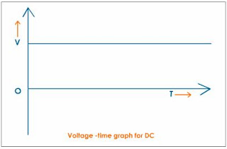
direct current wave form

dc voltage wave form

Main applications of direct current
direct current (DC) used in many application due to its unique feature that is its storage facility


1) Emergency supply or auxiliary services:

the use of direct current is due to the need to employ a back-up energy
source which allows the supply of essential services such as protection
services, emergency lighting, alarm systems, hospital and industrial services,
data-processing centres etc., using accumulator batteries, for example.
 

2)  Electrical traction:

the advantages offered by the use of dc motors in terms of regulation and of
single supply lines lead to the widespread use of direct current for railways,
underground railways, trams, lifts and public transport in general.
 

3) Particular industrial installations:

there are some electrolytic process plants and applications which have a
particular need for the use of electrical machinery.
Typical uses of circuit-breakers include the protection of cables, devices and
the operation of motors.

Considerations for the interruption of direct current


Direct current presents larger problems than alternating current does in terms
of the phenomena associated with the interruption of high currents. 

Alternating currents have a natural passage to zero of the current every half-cycle, which corresponds to a spontaneous extinguishing of the arc which is formed when
the circuit is opened.This characteristic does not exist in direct currents, and furthermore, in order to extinguish the arc, it is necessary that the current lowers to zero.
The extinguishing time of a direct current, all other conditions being equal, is
proportional to the time constant of the circuit T = L/R.
It is necessary that the interruption takes place gradually, without a sudden
switching off of the current which could cause large over-voltages. This can be
carried out by extending and cooling the arc so as to insert an ever higher
resistance into the circuit.
The energetic characteristics which develop in the circuit depend upon the
voltage level of the plant and result in the installation of breakers according to
connection diagrams in which the poles of the breaker are positioned in series
to increase their performance under short-circuit conditions. The breaking
capacity of the switching device becomes higher as the number of contacts
which open the circuit increases and, therefore, when the arc voltage applied is
larger.
This also means that when the supply voltage of the installation rises, so must
the number of current switches and therefore the poles in series.

Criteria for the selection of circuit-breakers for dc

 
For the correct selection of a circuit-breaker for the protection of a direct current
network, the following factors must be considered:
1.the load current, according to which the size of the breaker and the setting
for the thermo-magnetic over-current release can be determined;
2.the rated plant voltage, according to which the number of poles to be
connected in series is determined, thus the breaking capacity of the device
can also be increased;
3.the prospective short-circuit current at the point of installation of the breaker
influencing the choice of the breaker;
4.the type of network, more specifically the type of earthing connection.

Working principle of full wave bridge rectifier and digram

Full wave bridge rectifier - Rectifier is a circuit which convert alternating voltage into the direct voltage. There are three types o...

Popular Posts